The lateral loads are resisted by shear walls. BACKFILLING AGAINST BUILDING FOUNDATION WALLS SHALL BE DONE ONLY AFTER.

B Designed Slab Reinforcement Details Download Scientific Diagram
A slab is built to provide flat surfaces typically horizontal in building roofs floors bridges and other types of structures.

. Prepare a detailed structural drawing of one way continuous slab for a hall of clear dimensions 7m wide and 1177 m long use following data. THE TOP STEP MAY VARY FROM 16 INCHES - 24 INCHES FROM THE TOP OF CASTING. Introduction Properties of flat slab Determination of bending moment and shear force The direct design method Equilibrium frame method Slab Reinforcement Example 11 Example 12 Example 13.
315-20 PART C-FIGURES AND TABLES Fig. THE FOUNDATIONS UNDER THE CONCRETE BASE SLAB SHALL BE COMPACTED THROUGHLY AND A MINIMUM 200MM LAYER OF COURSE AGGREGATE SHALL BE PLACED OVER THE COMPACTED EARTH AND SEALED WITH 75MM THICK LAYER OF BLINDING CONCRETE. Maximum spacing of main bar is.
AASHTO Type II Prestressed Concrete Girder. Fcu 40 KNm2 fy 460KNm2. Foundation Detail wwwdouglascous 100 Third Street Castle Rock Colorado 80104 3036607497 Fax 3034797271 9292014 12 6 MINIMUM 18 MINIMUM BELOW GRADE ½ ANCHOR BOLTS A MINIMUM OF 7 INTO CONCRETE WITHIN 12 OF PLATE SPLICES AND 6 MAXIMUM SPACING.
M20 Type of steel. X 18 in edge beam dimensions 14 in. THE FIRST STEP SHALL BE PLACED 16 INCHES ABOVE THE BENCH.
The PDF covers the following topics. XBARREL SECTION - 12 INCH 16 INCH 24 INCH 32. The slab is without drops and is supported internally and on the external long sides by square columns.
4-Standard fabricating tolerances for bar sizes 3 through ll pg. The maximum diameter of bar used in slab should not exceed 18 of the total thickness of slab. 1a 1b or 1c as appropriate see below.
3-Typical details for one-way joist construction pg. General Notes 3 Wall Elevation Detail 4 RASTRA System Section 1 5 RASTRA System Section 2 6 RASTRA System Section 3 7 Truss. 6 mm 8 mm 10 mm 12mm and 16mm.
The imposed loading on the floor is 5 KNm2 and an allowance of 25KNm2 for finishes etc. Thickness of the slab is decided based on span to depth ratio specified in IS456-2000. This PDF file contains a chapter of 23 pages with various aspects of flat slabs including four example of flat slab design.
These are a perfect starting point for modification to meet your particular needs or just to use as is without changes. Use of its drawings computations or for failure resulting from the use of alternate materials or improper application or installation. Standard Drawings Standard specification drawing files in DGN and PDF formats.
MANHOLE STEPS SHALL BE ALIGNED OVER THE OUTGOING PIPE. 12 UNISTRUT SEISMIC BRACING DETAIL NTS 13SEISMIC BRACING DETAIL NTS 14 VENTILATION HOOD TO EXISTING W BEAM NTS 15 HANGER ATTACHMENT PHILADELPHIA PA 19107 ARAMARK CORPORATION Innovative Dining Solutions 4535 W. DIMENSIONS ARE NOT TO BE SCALED AND ONLY WRITTEN DIMENSION ARE TO BE FOLLOWED.
Crack Control in Slabs AS36002009. 5 inch wall 6. THE NOTES IN THIS DRAWING SHALL BE READ IN CONJUNCTION WITH ALL RELEVANT DRAWING PERTAINING TO THE BRIDGE.
For a slab fully enclosed within a building except for a brief period of weather exposure. 2 DETAILS AND DETAILING Chapter 8-Referenc es pg. This drawing is supplied solely to assist in the selection and application of CEMCO products.
Download Floor Slab Reinforcement Detail Sample 01 Download Floor Slab Reinforcement Detail Sample 02 Download Floor Slab Reinforcement Detail Sample 03. AASHTO Type II Prestressed Concrete Girder. Xconcrete and steel reinforcement shall conform to astm designation c478 xmanhole concrete strength to be 4000 psi or greater xmin.
The diameter of bar generally used in slabs are. Design the slab system shown in Figure 1 for an intermediate floor where the story height 12 ft column cross- sectional dimensions 18 in. Manhole wall base flat top slab thicknesses 4 ft id.
Connect NCDOT Resources Structures Standard Drawings 2018 English Stds. Standard detail drawings description page curb ramp 3-1 typical sidewalk 3-2 typical residential driveway approach 3-3 standard residential driveway opening 3-4 sidewalk driveway detail 3-5 concrete retaining wall detail 3-6 concrete curb gutter details 3-7 curb gutter inlet detail 3-8 commercial driveway opening 3-9. L-Typical details for one-way solid slabs pg.
X 27 in interior beam dimensions 14 in. TRUSS OR RAFTER CONNECTION 2 - 5 REBAR GRADE 60 MONOLITHIC. A floor slab in a building where stability is provided by shear walls in one direction N-S.
X 20 in and unfactored live load 100 psf. This drawing is generic in nature and should not be used in design or construction without an independent evaluation. Detail 13a - Brick Veneer Concrete Block Detail at Slab Edge for Load Bearing Wall Detail 14 - Brick Veneer Concrete Block Detail at Slab Edge Detail 15 - Membrane Air Barrier Detail at Movement Joint.
Where the ends of a slab are restrained and the slab is not freeto expand or contract in the secondary direction the minimum areaof reinforcement in the restrained direction is given by either Eq. The slab may be supported by walls by reinforced concrete beams normally cast monolithically with the slab from structural steel beams either by columns from the ground. Fe415 Clear cover.
UNLESS OTHERWISE SPECIFIED ALL DIMENSIONS IN MILLIMETER mm AND ALL LEVELS ARE IN METER m. RASTRA is a stay-in-place insulated concrete form that is structurally strong energy-efficient soundproof resistant to fire high wind mold and rodents and is made from 85 recycled materials. 2-Typical details for beams pg.
STEPS SHALL BE STEEL REINFORCED PLASTIC CONFORMING TO WSW 8401a. Prepare a detailed structural drawing of one way continuous slab for a hall of clear dimensions 7m wide and 1177 m long use following data Centre to centre distance of supporting beams 30 m Span of the beams 723m Beams are supported on walls of 023 m thickness Cs of beam 230 x 450 mm Grade of concrete. Unit 571 New Smyrna Beach FL 32128.
A slab is a flat element with depth D very small compared to its length and. The Leading Solar Magazine In India. These structural details dwg AutoCAD drawing download for concrete beam and slab system will help you to do any slab reinforcement detail drawing.
Minimum reinforcement is 012 for HYSD bars and 015 for mild steel bars. A collection of over 9230 2D construction details and drawings for residential and commercial application. One Hundred Twenty major categories of fully editable and scalable drawings and details in AutoCad Format.

Www Sefindia Org View Topic Need Of Detailing Awareness For Safe Structures
Roof Slab Drawing Pdf Pdf Architectural Elements Concrete

Two Way Slab Reinforcement Details Reinforced Concrete Concrete Slab Structural Drawing
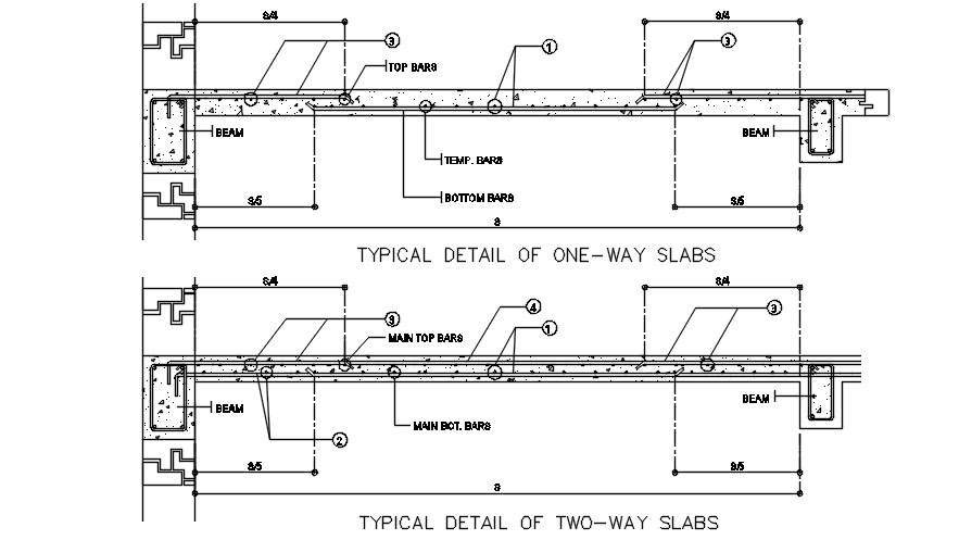
Typical Detail Of Two Way Slab Drawing Provided In This Autocad File Download This 2d Autocad Drawing File Cadbull

Typical Slab Reinforcement Structure Design Detail Autocad Dwg Plan N Design

Reinforcement Detailing Of Reinforced Concrete Slabs The Constructor

Details Of Slab Reinforcement And Beam Framing Plan Dwg File How To Plan Reinforcement Slab

Reinforcement Detail Of Floor Slab Dwg Drawing Thousands Of Free Autocad Drawings
0 comments
Post a Comment